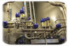
Alfa Laval mix-proof valves with ThinkTop control are used in this dairy application. The controls indicate individual valve status, e.g., open and closed valve, seat-lift, solenoid status and maintenance. Source: Wayne Labs.
Automated clean-in-place (CIP) takes a lot of manual work out of a cleaning operation, but the definition of what comprises a CIP system depends upon whom you ask. CIP implies that cleaning will be quick and effective with minimal operator input.
To accomplish CIP as quickly as possible, it is becoming more integrated with the process, says Gabe Miller, Sani-Matic business development manager. “There seems to be an increased interest in developing processes that are fully integrated with CIP to minimize changeover and sanitation time,” adds Miller. For example, a major beverage plant recently implemented a new process area that was designed to switch rapidly from process to CIP, and utilizes the process pumps as CIP return pumps. The circuits are isolated with mix-proof valves to prevent cross-contamination, and the process pumps are controlled by variable frequency drives (VFDs) to maintain CIP hydraulic balance.

In older diaphragm pumps (left), the outer piston/stainless plate was exposed; therefore product could get trapped between it and the diaphragm. In the newer design (right), the plate is embedded in the diaphragm, preventing trapped food products. The newer design has longer stroke, improving cleanability. Source: Wilden Pump & Engineering Co.
First things first
The original approach to this article was to look at the effects of newer cleaning chemicals on process and cleaning components: the pumps, valves, piping/tubing and spray nozzles. According to Woodley Wardell, BETE Fog Nozzle director of sales and marketing, the most important part of the CIP process-the part that actually does the cleaning-is often the last thing food processors think about. And that’s the spray nozzle or spray ball.Tim Oberg, Spraying Systems director of food and beverage markets, considers a simple definition of a CIP system to include a typical three-tank set of solutions, piping, valves and pumps that form a standalone system used in conjunction with a spray ball permanently mounted in a process vessel. Processors, however, often think of the spray ball itself as CIP. If the spray ball comes in contact with food, it has to meet sanitary guidelines such as 3A, FDA 21 CFR and/or possibly EHEDG (European Hygienic Engineering & Design Group) protocols, says Oberg.
While several suppliers (with plants in Europe) interviewed for this article indicated that European specifications vary from country to country, EHEDG strives to standardize hygienic standards for food production equipment in Europe. Even in the US, some specifications are less specific than others, according to Oberg. For example, FDA has no clear objection to the use of 316 Series stainless steel (SS) with minimal levels of chromium in pumps and valves-even though it’s not listed in 21 CFR. But he says FDA wouldn’t necessarily be keen with a cast 316 SS pump casing because it wouldn’t meet FDA surface finish requirements. At the same time, however, FDA is very clear about the use of elastomers and resins used in O-rings. Not all Teflon is FDA compliant, and in some cases, a 3A-compliant O-ring will not be the same as an FDA-compliant O-ring. Even more strange, according to Oberg, is that FDA has an objection to low-cost, brass nozzles that come in contact with food, but apparently they’re not an issue in breweries.
While processors won’t be using brass nozzles in food applications, they need to make several considerations when selecting spray nozzles, says Wardell. These include the liquid(s) used to do the cleaning, the product to be removed in the cleaning and its state (baked on or a greasy coating, for example), tank material and interior construction of the tank such as baffles and agitators, desired cycle time to do the cleaning, and flow and pressure rates of cleaning chemicals. To provide the right solution, a schematic diagram of the tank or vessel goes a long way in specifying the right nozzle, especially for an upgrade.
According to Rick Nelson, Ecolab director of engineering, “Sprays should be designed for specific applications. The dimensions, obstructions, tank outlet and associated lines connected to the vessel all drive the design performance parameters of flow, pressure, insertion depth, etc.” Each application should be evaluated as there is no magic bullet that covers every application, says Nelson.
An important issue to consider is price, says Wardell. “Cheap” may buy a nozzle that clogs quickly or a rotating nozzle with poor-quality bearings that seize after a few CIP cycles. Processors should weigh initial costs versus costs due to time-to-repair plus production downtime. Sometimes a solution might indicate Teflon or PVDF (polyvinylidene fluoride) spray balls rather than SS, especially if cleaning chemicals have any chlorine content.

In this beverage application, PMO-rated Aseptomag FS hygienic mix-proof valves switch from process into cleaning mode. When the valve seats are lifted individually for CIP procedures, a sub-atmospheric pressure is formed with the leakage chamber, guaranteeing product isolation. Source: Aseptomag.
Adjusting chemicals
Processors need as much protection as possible in combating harmful bacteria. Therefore, CIP temperatures have been trending upward, chemicals have been getting more aggressive, and system pressures have increased, says Ola Wesstrom, Endress+Hauser senior industry manager, food and beverage.At the same time, it seems environmental demands (weaker chemicals) would almost be at cross purposes with the needs for food safety (stronger chemicals). Yet, Nelson sees several trends centered on sustainability. Many local regulatory demands are putting an emphasis on effluents, and chemical companies have been responding with chemistries that provide less impact, such as reducing phosphoric and nitric acid levels and sodium content.
Reducing energy consumption and water usage, as well as improving employee safety, are also key drivers for sustainability, says Nelson. Altering chemistry can help reduce water usage. For example, chemistry with lower alkalinity requires a shorter rinse time and uses less water, while chemistry that allows for lower wash temperatures reduces rinse water usage to cool equipment, thus saving energy.
The latest versions of ECA generators provide free chlorine meeting Krones Construction Specification at 80ppm for 304 SS and 120ppm for 316 SS. Trustwater’s Model AQ outputs a level of 72ppm of free chlorine. Source: Trustwater.
Make your own chemicals
A recent development based on a several-decades-old technology may offer sustainable CIP solutions for some-but not all-food and beverage applications. “Regarding caustics and acids, the new ECA (electro-chemically activated) water systems can generate charged caustic and sanitizer from common sodium chloride salt,” says Miller. These systems were developed in Europe and have been implemented in many beverage processing facilities, significantly reducing energy, chemical and water consumption during CIP, as well as cleaning time. Although the sanitizer generated by ECA systems is suitable for practically all food and beverage CIP sanitizing, the caustic is being tested in other facilities for effectiveness, adds Miller. In the US, ECA systems have been FDA approved for use in beverage plants and are being tested for effectiveness on other soils as well.ECA systems use the principle of direct current (DC) electrolysis of salt water to generate both a sodium hydroxide (NaOH) caustic and, typically, a hypochlorous (HOCl) acid with potentially some free chlorine and hypochlorite in solution depending on pH.
According to Tony Peet, Trustwater’s senior vice president of sales, ECA technology lets processors make their own chemicals rather than purchasing them from a chemical manufacturer. This requires a one-time investment in the ECA generator, associated holding tanks, piping and valves. Processors can keep their existing CIP system; all that’s necessary is connecting the ECA system output lines to the CIP tanks. Bottling plants with Trustwater installed equipment have been able to eliminate the purchase of traditional CIP detergents and sanitizers, reduce CIP times by as much as 75 percent, decrease CIP energy consumption by up to 90 percent through the use of ECA solutions at ambient temperatures, reduce CIP water consumption by 40 percent and realize up to a 40 percent faster product changeover.
While there are pluses to ECA, Chris Brink, Johnson Diversey director of engineering food & beverage Americas, reminds processors that besides the initial equipment investment, there are ongoing maintenance costs associated with the equipment. In addition, there may be some applications where a chemical company can help a processor compensate for hard water and provide wetting agents to improve the coverage of the chemistry, which may be beyond the scope of some ECA providers. Two related issues may also be of concern. In some cases, ECA units may not produce enough NaOH to be injected at high rates. Most important, processors need to know the levels of detergent and sanitizers they are getting from the process to supply traceable information to regulatory agencies.
“No one technology has a silver bullet proposition,” says Robin Kirkpatrick, Radical Waters technical director. “But there are beverage applications where the ECA solutions have completely substituted for conventional chemicals without sacrifice to either cleaning or disinfecting ability.” Alternatively, dairy plants produce a very tenacious milk residue, which requires the reliability of the conventional chemicals, adds Kirkpatrick. For some applications, a combination of technologies may provide the best option. Radical Waters ECA solutions consist of a mixed oxidant cocktail as opposed to just a single element such as chlorine.
Another technique, which at first might seem to resemble ECA but involves passing alternating current (AC) through a water stream, produces an OH (hydroxyl) radical (not chlorine), according to David Wildes, BioIonix vice president of sales. This technology is typically applied to disinfecting filtered water streams of 40 to 600 gal./min. for rinsing vegetables and fruits and killing pathogens on the fly. While this technology could be applied to cleaning the returning rinse water in a CIP system, its main focus is on direct product contact. (For more on this technology, see “Engineering R&D: Do-it-yourself disinfectants,” FE, March 2010.)
Chemicals hard on equipment
To be more effective with killing bacteria, the increased use of high-temperature cleaning and sanitizing have had an impact on CIP equipment, says Nelson. Unless the high-temperature impact on the net positive suction head (NPSH) is recognized and properly addressed, the effect on the CIP supply and return pumps will almost inevitably result in poor performance with significant pump cavitation, which can lead to significant impeller and seal failures. Higher temperatures also have a service impact on seal and gasket materials, typically resulting in shortened life spans, says Nelson.The jury may be out in terms of whether a problem exists for ECA equipment and the levels of chlorine/chloride it generates. “Most dairies and other food processing plants rely on PAA (paracetic acid) and Quat (quaternary ammonium) for sanitizing,” says Brink, since HOCl causes rusting in many parts of the tank transfer and filling equipment, especially older model systems. In some cases, chlorine dioxide (ClO2) is used for water hygiene, but besides corroding and pitting equipment, chlorine in its various forms may find its way into some beverages, creating off-tastes.
Pumps take the heat
“One of the issues we routinely have with CIP is that customers want to run for longer periods, at higher temperatures with more aggressive chemicals. This is hell on pumps, especially any pump with rubber components,” says Michael Dillon, president of seepex Inc. As a result, seepex has worked with 3M/Dyneon to develop a new food grade elastomer with broader chemical resistance, temperature resistance to 350°F (depending on the normal food product temperature) and the same abrasion resistance as carbon-black-filled Buna rubber. “We think [this elastomer] will be a major help for most food processors because, from our perspective, CIP temperatures seem to vary a great deal. It may have to do with the way CIP tanks are heated or the actual operators. In general, we see CIP temperatures constantly creeping upward and causing problems,” adds Dillon.Pump complexity in general leads to cleaning complexity from both a CIP and COP (clean-out-of-place) perspective, says Wallace Wittkoff, Wilden Pump & Engineering Co. hygienic director. Some pumps must be made more complex for CIP, which can make them impractical for COP. A typical case is a pump with O-ring seals. These are very simple and reliable-and very suitable for COP, says Wittkoff. However, O-ring seals are generally not considered CIP-able, and therefore, mechanical seals need to be used. Many processors and pump manufacturers recognize the likelihood of mechanical seal damage increases when pumps are disassembled in the frequency required for COP.
For pumps that don’t use mechanical seals, assembly/disassembly may not be an issue at all, says Wittkoff. Some diaphragm pumps such as Wilden’s Hygienic series and Almatec Biocor series 3A/EHEDG units that are marked for CIP are easier to disassemble than non-CIP alternatives. These pumps are modeled after the diaphragm valve, which has the purity and cleanability required for biopharma applications. According to Wittkoff, a recent improvement in the diaphragm pump is the internalizing of the outer piston to hold the diaphragm in place. The SS plate is embedded in the diaphragm and eliminates a crevice and contamination point.
In general, 3A requirements actually aid in good pump design, eliminating potential trouble areas like cracks and crevices that could hold onto food particles and make CIP more difficult, says Randy Verges, Fristam Pumps senior application engineer. “The design must allow the cleaning fluid to get in and access all the areas to get the product out. That’s critical, especially with our FKL Series PD pumps,” he says. CIP-ability is a key feature of this pump. Processors don’t need to dissemble it and remove the rotors. Sizing the internal design of the pump to overcome shear/slippage issues with thin and thick products was overcome in the rotor/casing clearance, a solution that also aids in CIP.
As far as chemicals are concerned, Wittkoff recommends staying away from high chlorine levels in rinses because they pit SS. It’s one issue to deal with a product high in salt (chlorine) content such as ketchup, but he hasn’t had any processors asking for pumps to include high-end SS alloys just to withstand chlorine rinses; instead, it’s the concern for a product that might indicate Hastelloy or AL-6XN in pump casings or rotors.
Verges says pump components today are compatible with 98 percent of the chemicals in use. Infrequently he sees seal problems caused by potassium hydroxide, but chlorine is not usually a problem. The issue comes down to tradeoffs. If a processor sees corrosion in two to three years with standard grades of SS, selecting higher alloys may be worthwhile. But if equipment lasts for 10-15 years, it’s probably not worth the expense of higher alloys, which can raise the price of a pump by 200 to 300 percent over 300 SS. The issue, Verges says, is that while a processor might replace a single pump, as many as 20 valves may be connected to it. Should they be replaced? Many processors obsolete lines in 15 years, so replacing pumps and valves may not make sense, although it’s a case-by-case decision, he says.
Valves open to nasty chemicals
While valves in CIP applications tend to be 316 SS, from a manufacturer’s point of view, the aggressiveness of modern chemicals on SS, especially high acidity, the steel of choice is AL-6XN, says Ashok Nangpal, GEA Tuchenhagen technical applications manager. But the cost issue can make this choice prohibitive. In a PMO mix-proof valve, the additional metal used to make the valve can quickly multiply the price by 200 or 300 percent.Perhaps a more perplexing issue is the use of the newer foaming chemicals that penetrate areas in the valve that were not originally designed to accommodate them, adds Nangpal. For example, a control module is typically rated IP65, which means it’s rated to see water-not chemicals. If this foam enters an actuator, it can compromise the actuator’s functionality.
“In a mix-proof valve, the seat lift cleaning operation is critical,” says Paul V. Lopez II, Tyco Flow Control food and beverage industry manager. During normal cycling of the valve, “non-spillage-free” designs leave product in the leakage chamber. Also, if a “spillage-free” design does have a seat leak, product gets in the chamber as well and needs to be cleaned. Therefore, bi-directional seat cleaning is very important to maintaining a cleanliness standard, says Lopez.
The Achilles heel for mix-proof valve manufacturers is the ability to prove 100 percent that both seat lift operations have taken place, says Lopez. Mix-proof valve suppliers are left with one of two options: detecting that a signal has been sent to the solenoid initiating actuator movement-or detecting shaft or piston movement. Unfortunately, neither of these methods provides indication CIP fluid actually flowed through the leakage chamber. The solution is to monitor fluid discharge from the valve, which provides verification CIP fluid has actually passed through the leakage chamber. The same system can be used to monitor valve and body seal leakage, indicating when maintenance is required.
System issues: Poor design
While pumps and valves can be potential CIP challenges, other problems can exist in any system, which can help breed bacteria. For example, Nangpal describes a 100,000-gal. juice tank with a single spray ball at the bottom, which receives a flow of 100gpm. Unfortunately, with a 4- to 6-in. line going out, the 100gpm flow won’t get the job done.“I recently saw in one location a dead leg only a foot long,” adds Nangpal. “They completely forgot it was there, and then they complain when they have bio issues. It only takes a piece of pipe 6 in. long that isn’t cleaned to create problems.”
“The weak points in most processing systems are the process connections,” says Wesstrom. Poorly aligned or over-tightened connections cause gaps, crevices or obstructions (extruded gaskets) that are not being cleaned effectively, he adds. “There are new styles being developed in Europe to minimize or eliminate these problems, for example DIN-11864.”
Monitor for all the right reasons
Whether a processor uses a vendor-supplied chemical system or an internal ECA generator, there are real benefits to using instrumentation to prove adequate cleaning was accomplished. Not only are there electronic records for regulatory purposes, but in most cases, processors can also save on chemicals, energy and water usage. Unfortunately, according to Nangpal, only larger processors have set up in-line sensors to verify what’s going on with the CIP system. Smaller processors run lean and often spend too much money on unnecessary chemicals, excessive rinses and higher-than-necessary temperatures.In the past, in-line instrumentation such as vortex flow meters had issues with pressure drop and sensitivity to vibrations and turbulent flow, says Wesstrom. “Today, primarily magnetic flow meters are used which have no pressure drop and work over a much wider flow range. The key to effective CIP is to monitor both temperature and concentration of CIP detergent on the return line,” says Wesstrom. By using simple conductivity and temperature sensors, the amount of time and water/detergent used can be dramatically reduced while still achieving effective cleaning, he adds. “A client told me that the return on investment for him by switching from a purely timing-based CIP system to a concentration-based system was less than three months on a system used once a day.”
If a processor has an automated CIP system in place, chances are it is saving energy and water. Being green means not having to spend more money than necessary to keep equipment clean and free of bacteria.
For more information:
Ashok Nangpal, GEA Tuchenhagen, 410-750-8414, ashok.nangpal@geagroup.com
Chris Brink, Johnson Diversey, 513-759-0045, chris.brink@johnsondiversey.com
David Wildes, BioIonix, 608-838-0300, ext. 288, dwildes@bioionix.com
Rick Nelson, Ecolab, 651-293-2549, rick.nelson@ecolab.com
Gabe Miller, Sani-Matic, 800-356-3300, gabem@sanimatic.com
Mike Dillon, seepex, 937-864-7150, mdillon@seepex.net
Ola Wesstrom, Endress+Hauser Inc., 888-363-7377, ola.wesstrom@us.endress.com
Paul V. Lopez II, Tyco Flow Control, 717-314-1129, plopez@tycovalves.com
Randy Verges, Fristam Pumps, 800-841-5001, ext. 110, rverges@fristampumps.com
Robin Kirkpatrick, Radical Waters, 27-11-466-0610, robin@radicalwaters.com
Tim Oberg, Spraying Systems, 630-665-5000, tim.oberg@spray.com
Tony Peet, Trustwater, 952-288-0078, tony.peet@trustwater.com
Wallace Wittkoff, Wilden Pump & Engineering Co., 909-422-1700, wallace.wittkoff@pumpsg.com
Woodley Wardell, BETE Fog Nozzle, 413-772-2166, wward@bete.com
John Brink, POWER Engineers, 678-966-4484, john.brink@powereng.com
Applying EPA's ‘Reduce, Reuse and Recycle' to CIP
Three key sustainability principles listed by the EPA are reduce, reuse and recycle. According to Gabe Miller of Sani-Matic, CIP systems are being designed to achieve these three principles.• Reduce-CIP solutions can be reduced by implementation of liquid ring return pumps, which are self-priming, and the use of vortex breakers in process vessels to minimize the wasted hold-up volumes in the vessels during CIP. By implementing VFD speed control of CIP supply pumps, the CIP circuits can eliminate flooding of the vessels during CIP caused by improper balancing of the supply and return flows. By using analog level sensors in the CIP supply tanks, the water levels can be accurately controlled to minimize the addition of water to the system.
• Reuse-The trend in CIP systems has shifted over the last 25 years from single-use systems to reuse systems. This allows wash detergents to be reused for multiple CIP cycles, rather than being discharged to drain after each use. Reuse tanks have been getting larger to recover higher quantities, and the use of conductivity sensors in the return lines allows the systems to isolate the phases of the solutions, increasing the recovery of wash detergents and rinse water.
• Recycle-CIP systems are also capable of recovering product residues for reprocessing. This is especially true in ice cream and cheese processing. For other food processes with higher solids, projectile recovery systems (commonly called “pigging systems”) are being used increasingly to recover the residues in pipelines for reprocessing, prior to CIP. 3A is in the process of developing a sanitary standard for these pipeline product recovery systems, to ensure they are designed to maintain the quality and safety of the food products.
Proper piping layout for CIP systems
According to John Brink, senior project manager with POWER Engineers, food and beverage processors should incorporate the following in CIP installations:• Slope the pipes-The layout of the system piping must allow for an appropriate degree of slope to fully drain the system during and after the CIP process steps. Process and CIP piping should be designed to slope toward the specified drain points in the system. The degree of slope depends on material being removed from the piping and in some cases will require as much as 1/4 inch per foot.
• CIP fluid velocity-The fluid velocity in the process piping must be kept high enough to allow the shear forces to adequately scour the interior piping surface to remove deposits on the pipe walls. The amount of deposit buildup on the interior walls of the piping should be considered during system design to insure adequate fluid velocities are maintained to allow thorough cleaning of the piping. CIP supply and return pumps should be sized to keep the fluid velocities between 5 and 8 ft/s. Instrumentation should be placed in the piping system to record the supply pump pressure and flow rate.
• No dead legs-Ensure there are no dead legs in the system where CIP fluids can’t flow. This is important for pipe routing and instrumentation mountings. The dead ends for instrumentation mounting should not exceed 1.5 times the pipe diameter.
• CIP cycle times-The duration of each of the CIP steps also needs to be addressed during the piping design to ensure the steps are long enough to provide effective cleaning of the piping.
• Monitoring-Sensor locations for temperature, concentration, etc. must also be addressed during piping design to shorten each step to the minimum thus conserving water and CIP chemicals. Usually the temperature and conductivity sensors are installed in the system return piping to ensure that the entire system has seen the design conditions.
• Material selection-Care must be taken to select the appropriate piping material for the system that can withstand the process conditions. The most common materials for CIP piping are 304 and 316 stainless steel.
